Radial Radiator Concept

I recently had an idea to integrate a water pump and radiator into a package which could fit inside of a duct, such as the air intake of a car. The idea was to replace the conventional radiator, thermostat and water pump. Waste heat can be reingested into the air intake - this isn't a new idea. I just thought it would be fun to flesh out some models of an interesting concept.
|
|
An overview of the layout is shown at right. The geometry is all relational, such that parameters can be changed to suit the target application.
|

|
|
The cross-section shows how the central pump pushes the coolant outward through the spiral-like channels. Perfect spirals were not used because of the difficulty in near-tangent interfacing between the ducts and manifolds. The scroll collects the post-exchange fluid for recycling. Fins are notionally drawn as spirals normal to the ducts.
|

|
|
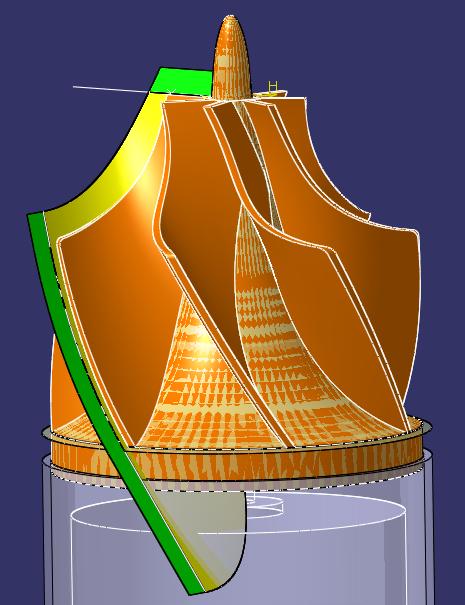
The rotor was fun to model. A lot of detail, and tricky to make it as relationally robust as possible. The critical angles are all parametric, and the blades are trimmed by a bounding surface which is also generative.
|
|
One interesting thing about this centrifugal pump design is that it actually also acts as a diffuser - that is, the outlet is larger than the inlet.
Also, it could be an advantage in that there must be a sweet-spot between fluid velocity and total heat transferred. That is, at lower velocities the hot fluid spends more time in the presence of the cool stream, but has a lower convective heat transfer coefficient (h). But maybe faster is just always better, because all that matters is h. Warrants more thought.
A fluids professor of mine once said "it's hard to design a centrifugal pump that doesn't work." But that was an introduction to a lesson on efficiency. In some more recent work I've used centrifugal layout software to design more realistic turbines, and even printed/tested them.
|

|
|
Some of the construction geometry for the vane is shown at right. It's an oversized sweep that is then trimmed by a couple planes and surfaces.
Note that I've chosen to sweep the outlet, an angle I'm calling "sway", in order to ensure that the blades never fully choke the outlet ports on the manifold. If that were to happen you would get some really odd water hammer effects that could cause fatigue. I've never seen a rotor like this, and am curious how this "sway" parameter would affect performance.
An integrated potted electric motor drives the rotor. It contains a built-in control circuit that regulates turbine speed as a function of the coolant and air temperatures.
|
|
|
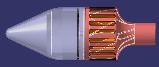
The interface between the inner radiator manifold and the rotor is shown at right. This demonstrates the concept of avoiding port blockage by use of a sway angle on the rotor outlet.
It could be better to sway the ports instead of the rotor. In that case the radiator ducts would not be parallel to the external flow, which could enhance the heat transfer coefficient on the outer surface. Research indicates that about 15° of inclination is optimal from a forced convection standpoint.
|

|
The integrated motor and rotor housing are shown at right. The two shrouds thread together for seamless integration and sealing. Although the motor is potted into its housing, this makes the rotor at least serviceable. The rotor is fiber reinforced plastic for weight and cost savings.
|
|
The parametric nature of the model is demonstrated below, with various parameters changed to fit a large and small installation scenario. The scale is the same left and right.
|
|


